You are browsing camaro6 
 02-27-2024, 12:34 PM
|
#1 |
 Drives: 2000 WS6 Join Date: Dec 2014
Location: AZ
Posts: 499
|
DIY Anti-theft alarm and starter disable
After the seeing the concerns across at least 4 different threads about the recent rash of thefts of our beloved cars, I thought I'd start documenting the efforts of myself and my friend "J". J is a former professional audio/alarm installer who now works in IT, and I know professionally. He deserves the credit for this design and honestly did most of the research, editing, and documentation. He's not a member of this forum but I'm grateful for his help and I couldn't have done this without him.
We wanted to create a DIY implementation with some inexpensive parts, and provide detailed instructions that would allow a non-expert competent DIY person to follow. I think the total cost is under $100 assuming you have all the required tools. Everything is available for purchase on Amazon. We placed 10k resistors between the Data1+ and Data1- dummy OBD pins. likewise the Data2 pins. This also an optional step to the implementation. Thanks to Keep_hope_alive for this suggestion: "The intent of the 10k ohm resistors, one from each data pin to associated signal ground, is to make the reader think there is a circuit but it won't understand why it doesn't read any data. It prevents errors from an open circuit. The 10k ohm size ensures that nothing is damaged and is close to the input resistance of the actual circuit." So, we fake the ECU circuit with the 10k resistors. The cloning tool sends out 2-5VDC, and establishes OSI layer 2 connectivity (with itself) for a serial connection. L3 and above obviously will not work, but this serves as another layer of obfuscation to confuse a thief into believing the dummy port may be operational. Additionally, I recommend putting a cheap (3D printed) OBD2 lock on your dummy cable. It will help convince/distract a thief that the port was worth protecting, slow them down, and any damage done removing the lock will be on the dummy port. With the relay boards in "MODE 12", once triggered, they will keep a persistent output condition even when the offending OBD reader is removed, until either the timers elapse or the reset button is pressed. If everything in this system were ripped out, the car will not start. With everything in place, the car will start and remote start should still work. The relay boards have a lower power mode with nothing displayed and have a non-volitile memory if they lose continuous power, they should resume operating how they were last configured. Here's a demo video of the final operating model on a bench: We included two independent timer relays to control the starter lockout and the siren duration. You could do the project with a single timer relay board, with the same duration applied to the siren and the starter lockout. Tools: Wire stripper, crimper, multimeter, 12VDC source (old battery for bench testing), soldering iron, butane lighter, pin removal tool (optional), Ferrule crimper (optional). Materials: Multiple colors of wire, at least red and black. 16-18 AWG is more than adequate. Ferrule crimps (optional). Solder melt butt connectors. Wago clips (optional), 10k Ohm resistors, 5A blade fuses shrink tubing. Parts: 2X Timer boards Posi-Tap connectors OBD2 Pigtail Momentary Reset Switch 5 Pin Relay Harness (optional, only need one) Mini Piezo Siren Fused distro block 5 pin relay 5pin single pole double throw Waterproof to handle any kind of moisture that might or might not hit it 40amp capable That's all I can provide for now, more videos and drawings will follow. Feel free to ask questions and hopefully someone else will benefit from this. Last edited by Capricio; 08-15-2024 at 03:40 PM. Reason: added 5A blade fuses with link |

|

|
|
03-13-2024, 01:47 PM
|
#2 |
|
Geoff

Drives: 2020 ZL1 Green Join Date: May 2013
Location: Houston
Posts: 1,743
|
Thank you for this
__________________
|
|
|
|
|
03-17-2024, 01:02 PM
|
#3 | |
|
Drives: 2000 WS6 Join Date: Dec 2014
Location: AZ
Posts: 499
|
Quote:
We finally got the entire system installed yesterday. It works perfectly and we should have a short video soon. Had a funky issue with a ground loop using the big relay grounded through the fuse block bus, so we gave it it's own ground. We also used the opportunity to install a footwell lighting kit. We'll try to get the schematic, videos of the finished install, placement of components, and programming the relay boards. We fused everything for 5A. We took 12V constant positapped from the real OBD and positapped ground(s) from wires going to lug near the dead petal behind some carpeting. You could be more ambitious and find a better constant power from the power plug in the center console or the big wire in the BCM. Most of the parts fit in the cavity accessible by removing the side panel from the dash, where you can see a color legend for the BCM plugs, below the vent. We ran the reset button to the glovebox and taped it the top so it's only visible by getting your head pretty low, but can easily be found through tactile/feeling. We placed the siren in the dash below steering column blasting right into the driver's face, it does not impede the range of motion of the tilt-steering. Advantages of this setup:
Last edited by Capricio; 04-20-2024 at 01:29 PM. |
|
|
|
|
|
03-17-2024, 04:10 PM
|
#4 |
     
Drives: 2020 Chevy Camaro ZL1 Join Date: Apr 2023
Location: Calgary Canada
Posts: 1,629
|
Nice work, I love this kind of stuff.
|
|
|
|
|
03-17-2024, 04:55 PM
|
#5 |
|
Drives: 2000 WS6 Join Date: Dec 2014
Location: AZ
Posts: 499
|
|
|
|
|
|
03-17-2024, 06:38 PM
|
#6 |
|
Drives: Garnet Red - 20 ZLE Join Date: Jun 2016
Location: Southern California
Posts: 1,010
|
|
|
|
|
|
03-28-2024, 05:17 PM
|
#7 |
|
Drives: 2000 WS6 Join Date: Dec 2014
Location: AZ
Posts: 499
|
K9 Body Control Module X4 (the black one, under your driver's side dash)
Pin: 15 Color: GN /VT Circuit: 5199 Run/Crank Relay Coil Control |
|
|
|
|
04-09-2024, 04:25 PM
|
#8 |
|
Got mine!

Drives: 2021 LT1 RS - Orange Crush Join Date: Mar 2011
Location: Fallbrook, CA
Posts: 1,316
|
Not sure with the last post meant, but I'm ready for more info on this project.
__________________
Camaro lover since 1984 when I got my first car a 1978 Camaro LT with a 2 barrel carb on 305 V8... yes I put in a 350 with a 4 barrel.
|

|
|
|
04-09-2024, 07:17 PM
|
#9 | |
|
Drives: 2000 WS6 Join Date: Dec 2014
Location: AZ
Posts: 499
|
Quote:
Hopefully J will find time to finish up the schematic soon. Sorry it's taking a while. We also have a video that will describe how to configure the relay boards. |
|
|
|
|
|
04-10-2024, 07:22 AM
|
#10 | |
|
Probably doesn't like you

Drives: 2022 WCT ZL1 M6 Join Date: Jun 2015
Location: Boston-ish
Posts: 1,316
|
Quote:

__________________
I hope the 6th gen Camaro has a melodious horn trumpet. I'll tootel it at the ladies, yelling out "Hi hi." - RenegadeXR
كافر ΜΟΛΩΝ ΛΑΒΕ железобетонное очко Quod gratis asseritur, gratis negatur. There is an unequal amount of good and bad in most things, the trick is to work out the ratio and act accordingly. |
|
|
|
|
|
04-10-2024, 10:19 AM
|
#11 | |
|
Got mine!
Drives: 2021 LT1 RS - Orange Crush Join Date: Mar 2011
Location: Fallbrook, CA
Posts: 1,316
|
Cool. Thanks man. Can't wait!
Quote:
__________________
Camaro lover since 1984 when I got my first car a 1978 Camaro LT with a 2 barrel carb on 305 V8... yes I put in a 350 with a 4 barrel.
|
|
|
|
|
|
04-15-2024, 04:21 PM
|
#12 |
|
Drives: 2000 WS6 Join Date: Dec 2014
Location: AZ
Posts: 499
|
Schematic:
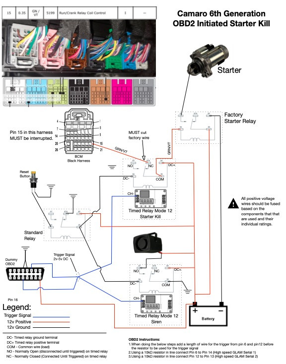 I highly recommend building this out on a bench before trying to install in the car. Just need a battery source, ground, and multimeter testing continuity where the coil activation wire would be. Also, if you're going to suffer through standing on your head in the passenger footwell to install a reset button like we did in the glovebox area, now is a great time to consider installing a footwell lighting kit (for cars with ambient lighting kits) and/or getting after the OnStar board. Last edited by Capricio; 04-16-2024 at 10:02 AM. |
|
|
|
|
05-01-2024, 12:41 PM
|
#13 |
 Drives: triple black 98Z Join Date: Mar 2012
Location: Lost Angeles
Posts: 20
|
Wow, great job. I basically just spent 1300 for this Saturday. LOL and with IGLA I have a pin sequence to enter before starting got it down to a few seconds but still.
|
|
|
|
|
05-01-2024, 04:04 PM
|
#14 | |
|
Drives: 2000 WS6 Join Date: Dec 2014
Location: AZ
Posts: 499
|
Quote:
We may try to provide one more video on configuring the relay boards since we recorded that process, but there are already videos available for that. Using Mode 12 is the most important part. |
|
|
|
|
|
|
|
|
|
Post Reply
|
|
|