Planned: Stabilizing Alternator Output at ~13.8V on my 2023 Camaro 1SS (Smart Charging Bypass for Audio)
Im in the middle of building out my audio system and want consistent charging voltage in the 13.814.0V range for optimal amplifier performance without overcharging the AGM battery. Like most modern GMs, the 2023 Camaro has a smart charging system that varies alternator output. Heres what Ive learned and my plan to fix it.
What We Know About the System
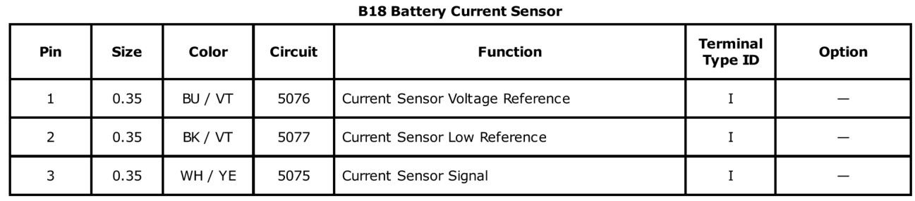
The Camaro uses a Hall-effect Battery Current Sensor on the negative battery cable in the trunk. Its a 3-wire sensor (5V reference, ground, and PWM signal) that sends a ~128 Hz PWM signal (duty cycle typically 595%) to the Body Control Module (BCM). The BCM uses this data along with voltage and temperature to control the alternator via the L-terminal.
From the service manual, the alternator responds as follows:
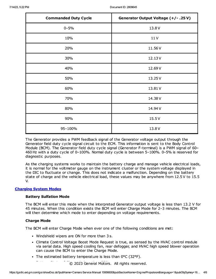
05% or 95100% → 13.8V (diagnostic/fallback mode)
~6070% range → roughly 13.814.0V (my target zone)
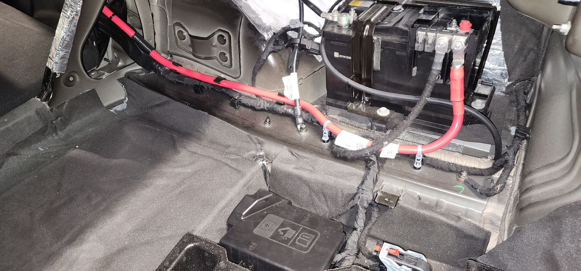
When I temporarily unplugged the sensor, voltage climbed to 14.8V too high for comfortable long-term use. You can see the current sensor in this photo (on the ground wire):
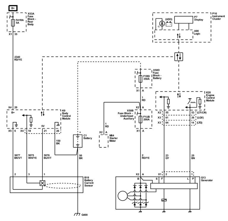
The sensor is in the schematic as shown here:
The BCM has fallback logic: when it loses the current sensor signal, it switches to voltage-only load shed and idle boost tables.
Options I Considered
1. Simply unplug the sensor Easiest, but gave me 14.8V (too aggressive).
2. Route amp negative cables through the sensor loop Keeps everything stock and lets the BCM see real load. Issue here is the stock ground wire current direction may be different than the audio system current direction, it lengthens my ground wire substantially, and will still result in voltage fluctuations.
3. Resistor bias on the signal wire Doesnt return PWM.
4. 555 timer PWM circuit Viable, but less precise and unable to be tuned or adjusted easily.
5. Arduino Nano Every PWM simulator Cleanest and most adjustable solution. Allows precise 128 Hz PWM with live visual feedback.
My Planned Approach
Ive ordered a 3-pack of Arduino Nano Every boards. Ill use one to build a PWM simulator that tricks the BCM into seeing a moderate constant load (~6070% duty cycle). This should hold voltage steady in my desired range while keeping the BCM in normal operating mode as much as possible.
Hardware Ill be using:
Arduino Nano Every
TM1637 4-digit 7-segment display (to show real-time duty cycle percentage and another for voltage)
10kΩ potentiometer for easy tuning
Pushbutton to engage 7-segment displays
Small perfboard + enclosure for trunk mounting
Planned Wiring:
Power and ground taken from the sensors 5V reference
PWM output on D9 injected into the signal wire (5076 BU/VT) going to the BCM
TM1637 display on D2/D3
Ill start with a reader board to see exactly what frequency the factory current sensor outputs. That process is outlined in this video:
https://youtu.be/mruUknOU7CI?si=a7qSuHN_wT3ieFgh
Then, Ill the build the Nano arrangement and set to ~65% duty cycle and fine-tune while monitoring battery voltage with a multimeter and OBD scanner.
Next Steps in my Build
1. Use a reader sketch to measure the actual frequency and duty cycle behavior on my car
2. Build and install the PWM simulator
3. Install the new Platinum AGM H6 battery
4. Tune for stable 13.814.0V under heavy audio load
5. Monitor load shed / idle boost behavior and long-term reliability
Ill update this thread with progress, test results, final code, photos, and any lessons learned. If anyone has done something similar on a 6th-gen Camaro (or other GM), Id love to hear your experiences.