You are browsing camaro6 
 07-14-2023, 08:21 PM
|
#1 |
|
Electrical Engineer

Drives: 2023 1SS A10 Black Join Date: Apr 2022
Location: Illinois
Posts: 779
|
Cylinder Deactivation Explained (Service Manual Description)
The following is from the Service Manual available on ACDelcoTDS, the selected vehicle is a 2023 6.2L LT1.
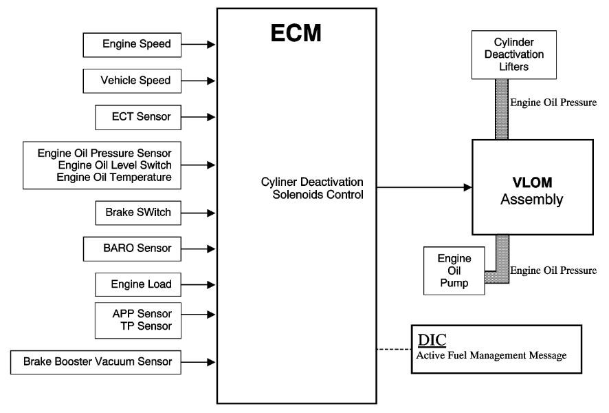 To provide maximum fuel economy under light load driving conditions, the engine control module (ECM) will command the cylinder deactivation system ON to deactivate engine cylinders 1, 7, 6, and 4, switching to a V4 mode. The engine will operate on 8 cylinders, or V8 mode, during engine starting, engine idling, and medium to heavy throttle applications. The conditions listed below determine when cylinder deactivation is enabled. Engine has been running for greater than 30 s Engine speed is between 700 and 2800 rpm Engine oil pressure is between 187455 kPa (2766 psi) Engine coolant temperature is between 40129°C (100264°F) Engine oil temperature is between 16128°C (61263°F) Throttle angle is 6% or less Ignition voltage is greater than 11 V Transmission is not in first, second, or reverse gear Vehicle speed is greater than 25 kph (15.5 mph) Brake booster pressure is greater than 42.0 kPa (6 psi) Vehicle is not in fuel shut off mode Vehicle is not in heater performance mode Vehicle is not in tip in bump acceleration mode Vehicle is not in oil aeration mode Vehicle is not in low range (if equipped) When cylinder deactivation is commanded, the ECM will determine what cylinder is firing and begin deactivation on the next closest deactivated cylinder in firing order sequence. For example, if cylinder number 1 is on its combustion event when cylinder deactivation is commanded ON, the next cylinder in the firing order sequence that can be deactivated is cylinder number 7. If cylinder number 5 is on its combustion event when cylinder deactivation is commanded ON, then the next cylinder in the firing order sequence that can be deactivated is cylinder number 4. Active Fuel Management Valve Lifters When operating in V8 mode, the active fuel management valve lifters function similar to the non-active fuel management valve lifters. The active fuel management oil manifold solenoids are in the closed position, with no pressurized oil directed to the valve lifters. The pushrod (1) travels upward and downward to actuate the rocker arm and valve. The spring loaded locking pins (5) of the lifter are extended outward and mechanically lock the pin housing (4) to the outer body of the valve lifter (3). When the active fuel management system is commanded ON, the ECM will direct the solenoids of the oil manifold to open and direct pressurized oil to the valve lifters. Oil travels through the valve lifter oil manifold and engine block oil galleries and enters the inlet port (6) of the valve lifter. When operating in V4 mode, pressurized oil forces the locking pins (11) inward. The pushrod (7) remains in a constant position and does not travel upward and downward. The outer body of the lifter (9) moves upward and downward independently from the pin housing (10). The valve lifter spring (8) retains tension on the valve train components to eliminate valve train noise. When the active fuel management system is commanded OFF, the ECM directs the solenoids of the oil manifold to close, stopping the flow of pressurized oil to the valve lifters. The oil pressure within the lifter will decrease and the locking pins will move outward to mechanically lock the pin housing and outer body. Although both intake and exhaust valve lifters are controlled by the same solenoid in the valve lifter oil manifold assembly, the intake and exhaust valves do not become deactivated at the same time. Cylinder deactivation is timed so that the cylinder is on an intake event. During an intake event, the intake cam lobe is pushing the valve lifter upwards to open the intake valve against the force of the valve spring. The force exerted by the valve spring is acting on the side of the lifter locking pins, preventing them from moving until the intake valve has closed. When the intake valve lifter reaches the base circle of the camshaft lobe, the valve spring force is reduced, allowing the locking pins to move, deactivating the intake valve. However, when cylinder deactivation is commanded ON, the exhaust valve for the deactivated cylinder is in the closed position, allowing the locking pins on the valve lifter to move immediately, and deactivate the exhaust valve. By deactivating the exhaust valve first, this allows the capture of a burnt air/fuel charge, or exhaust gas charge, in the combustion chamber. The capture of exhaust gases in the combustion chamber will contribute to a reduction in oil consumption, noise and vibration levels, and exhaust emissions when operating in V4 mode cylinder deactivation mode. During the transition from V8 to V4 mode, the Fuel Injectors will be turned OFF on the deactivated cylinders. To help prevent spark plug fouling, the ignition system secondary voltage or spark is still present across the spark plug electrodes on the deactivated cylinders. If all enabling conditions are met and maintained for cylinder deactivation operation, the ECM calibrations will limit cylinder deactivation to a cycle time of 10 minutes in V4 mode, then return to V8 mode for 1 minute. Switching between V8 and V4 modes is accomplished in less than 250 milliseconds. The 250 milliseconds includes the time for the ECM to sequence the transitions, the response time for the valve lifter oil manifold assembly solenoids to energize, and the time for the valve lifters to deactivate, all within 2 revolutions of the engine crankshaft. 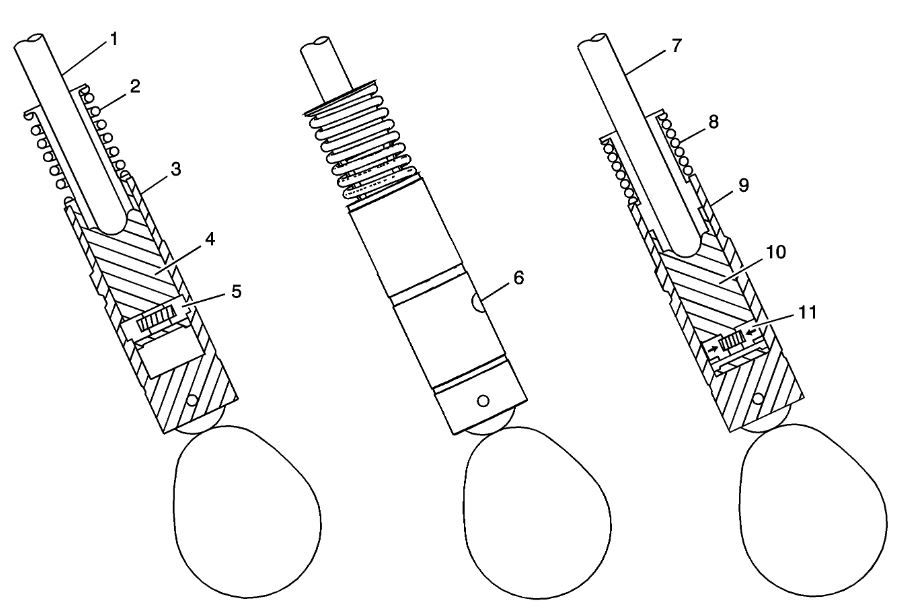 Valve Lifter Oil Manifold Assembly The cylinder deactivation system uses an electro-hydraulic actuator device called the valve lifter oil manifold assembly. The valve lifter oil manifold assembly is bolted to the top of the engine valley, below the intake manifold assembly. The valve lifter oil manifold assembly consists of 4 electrically operated normally closed solenoids. Each solenoid controls the application of engine oil pressure to the intake and exhaust valve lifters on the cylinders selected to deactivate. Engine oil pressure is routed to the valve lifter oil manifold assembly from an internal oil passage on the rear of the cylinder block. All 4 valve lifter oil manifold assembly solenoids are connected in parallel to a fused ignition 1 voltage circuit, supplied by the powertrain relay. The ground or control circuit for each solenoid is connected to a low side driver internal to the engine control module (ECM). When all enabling conditions are met for cylinder deactivation, the ECM will ground each solenoid control circuit in firing order sequence, allowing current to flow through the solenoid windings. With the coil windings energized, the solenoid valve opens, redirecting engine oil pressure through the valve lifter oil manifold assembly into 8 separate vertical passages in the engine lifter valley. The 8 vertical passages, 2 per cylinder, are connected to the valve lifter bores of the cylinders to be deactivated. When vehicle-operating conditions require a return to V8 mode, the ECM will turn OFF the control circuit for the solenoids, allowing the solenoid valves to close. With the solenoid valves closed, engine oil pressure in the control ports is exhausted through the body of the solenoids into the engine block lifter valley. The housing of the valve lifter oil manifold assembly incorporates several bleeds in the oil passages to purge any air trapped in the valve lifter oil manifold assembly or engine block. To help control contamination to the hydraulic circuits, a small replaceable oil screen is located in the valve lifter oil manifold assembly oil inlet passage, below the oil pressure sensor. The oil pressure sensor is a 3-wire sensor which provides oil pressure information to the ECM. During service, use extreme care in keeping the valve lifter oil manifold assembly free of any contamination or foreign material. Cylinder deactivation may be inhibited for many reasons including the following: Engine coolant temperature out of range for cylinder activation Engine vacuum out of range Brake booster vacuum out of range Transmission gear incorrect or shift in progress Accelerator pedal out of range or rate of pedal application to fast Engine oil pressure and temperature out of range Engine speed out of range Vehicle speed out of range Minimum time in V8 mode not met Maximum V4 mode time exceeded Decel fuel cutoff is active Reduced engine power is active Torque management is active Catalytic converter over temperature protection is active Piston protection is active, knock detected Cylinder deactivation solenoid driver circuit faults
__________________
2023 1SS A10 Black NPP/C2U/H72 - Daily Driver
Historically an Accord and Camry owner with self-performed maintenance/repair. 1100: 5/3/22 . . . . . . . 2000: 6/25/22 . . . . . .4000: 8/17/22 . . . . . . . 6000: 9/10/22 Daily Driver mileage update: 22k mi. @ April 2024 New Engine @ 22,600 Build Log: https://www.camaro6.com/forums/showt...6#post11353116 |

|

|
|
07-14-2023, 08:31 PM
|
#2 |
|
Electrical Engineer
Drives: 2023 1SS A10 Black Join Date: Apr 2022
Location: Illinois
Posts: 779
|
System Operation
General Motors Active Fuel Management engine control system has the ability, under certain light load driving conditions, to provide maximum fuel economy by deactivating 4 of the engines 8 cylinders. The engine will normally operate on 8 cylinders in V8 mode during starting, idling, and medium or heavy throttle conditions. When commanded ON, the engine control module (ECM) will direct the active fuel management system and deactivate cylinders 1 and 7 on the left bank and cylinders 4 and 6 on the right bank, forcing V4 mode. The valve lifter oil manifold assembly (1) is bolted to the top of the engine block beneath the intake manifold assembly. The oil manifold consists of 4 electrically operated and normally-closed solenoids (4). Each solenoid directs the flow of pressurized engine oil to the active fuel management intake and exhaust valve lifters (5). When enabling conditions are met for active fuel management operation, the ECM will ground each solenoid control circuit in firing order sequence, allowing current to flow through the solenoid windings. With the windings energized, the solenoid valves open and direct pressurized engine oil through the valve lifter oil manifold into 8 vertical passages in the engine block lifter valley. The 8 vertical passages, 2 per AFM cylinder, direct pressurized oil to the valve lifter bores of the cylinders to be deactivated. When vehicle operating conditions require a return to V8 mode, the ECM will turn OFF the ground circuit for the solenoids, allowing the solenoid valves to close. When the solenoid valves are closed, remaining oil pressure is exhausted through the bleed passages of the valve lifter oil manifold into the engine block lifter valley. The housing of the oil manifold incorporates a vent orifice that continuously purges trapped air from the manifold To help control contamination within the active fuel management hydraulic system, a small replaceable oil filter (3) is located in the valve lifter oil manifold oil inlet passage. The oil pressure sensor (10) monitors engine oil pressure and provides information to the ECM. 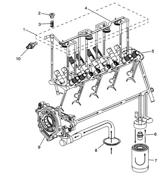
__________________
2023 1SS A10 Black NPP/C2U/H72 - Daily Driver
Historically an Accord and Camry owner with self-performed maintenance/repair. 1100: 5/3/22 . . . . . . . 2000: 6/25/22 . . . . . .4000: 8/17/22 . . . . . . . 6000: 9/10/22 Daily Driver mileage update: 22k mi. @ April 2024 New Engine @ 22,600 Build Log: https://www.camaro6.com/forums/showt...6#post11353116 |
|
|
|
|
07-14-2023, 08:43 PM
|
#3 |
|
Electrical Engineer
Drives: 2023 1SS A10 Black Join Date: Apr 2022
Location: Illinois
Posts: 779
|
So, they mention a small filter. This is the description for filter replacement:
Note: Do not allow dirt or debris to enter the oil passages of the manifold. Plug, as required. Remove the oil pressure sensor (3). Remove the valve lifter oil manifold plug (1) and oil filter (2). 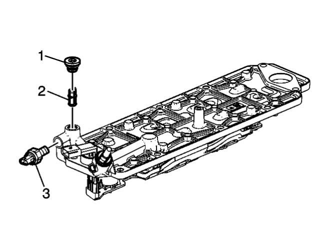 Another image: 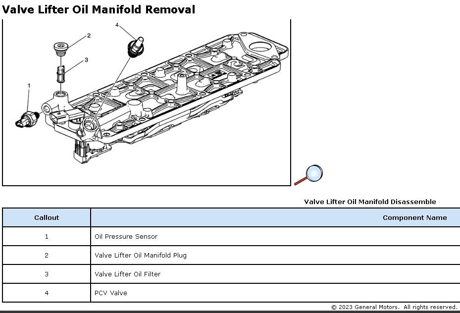
__________________
2023 1SS A10 Black NPP/C2U/H72 - Daily Driver
Historically an Accord and Camry owner with self-performed maintenance/repair. 1100: 5/3/22 . . . . . . . 2000: 6/25/22 . . . . . .4000: 8/17/22 . . . . . . . 6000: 9/10/22 Daily Driver mileage update: 22k mi. @ April 2024 New Engine @ 22,600 Build Log: https://www.camaro6.com/forums/showt...6#post11353116 |
|
|
|
|
07-14-2023, 09:26 PM
|
#4 |
|
Electrical Engineer
Drives: 2023 1SS A10 Black Join Date: Apr 2022
Location: Illinois
Posts: 779
|
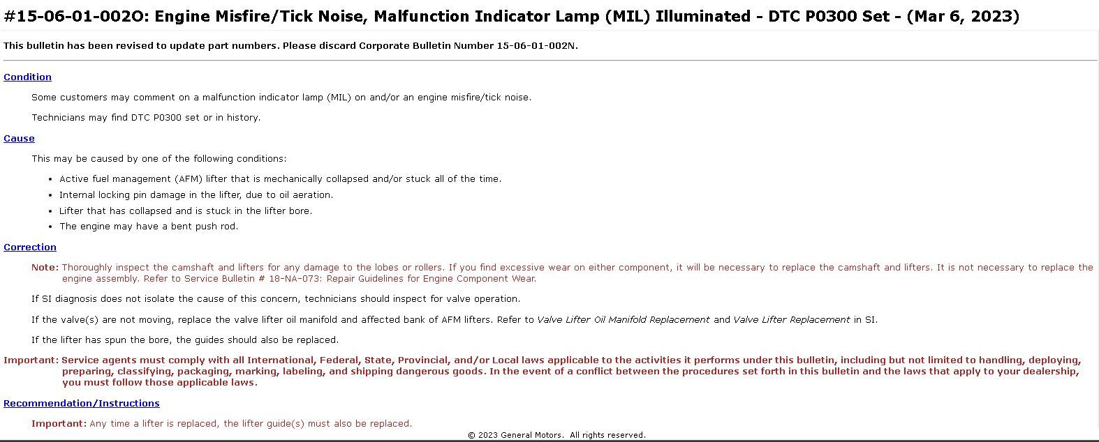
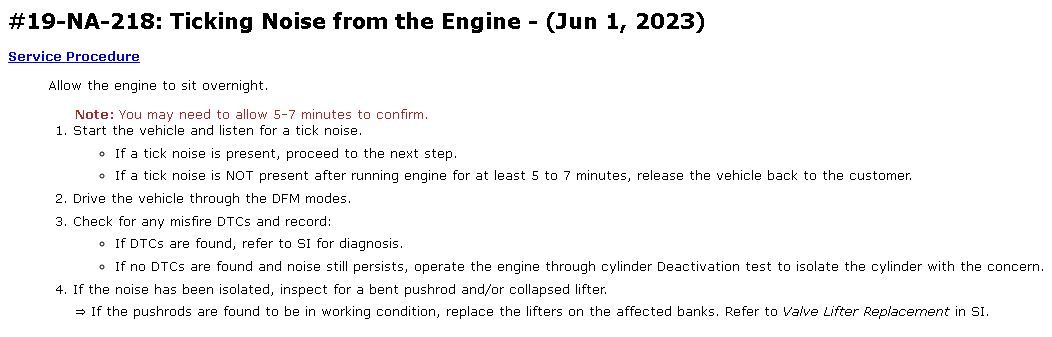
And there are two Bulletins associated with lifter issues:
__________________
2023 1SS A10 Black NPP/C2U/H72 - Daily Driver
Historically an Accord and Camry owner with self-performed maintenance/repair. 1100: 5/3/22 . . . . . . . 2000: 6/25/22 . . . . . .4000: 8/17/22 . . . . . . . 6000: 9/10/22 Daily Driver mileage update: 22k mi. @ April 2024 New Engine @ 22,600 Build Log: https://www.camaro6.com/forums/showt...6#post11353116 |
|
|
|
|
08-02-2023, 02:27 PM
|
#5 |
|
Electrical Engineer
Drives: 2023 1SS A10 Black Join Date: Apr 2022
Location: Illinois
Posts: 779
|
Exhaust Tail Pipe Flow Control System Description and Operation
Engine Exhaust Flow Valve System The engine exhaust flow control valve system has two subsystems: The exhaust tail pipe flow control valve system. Also known as the exhaust sound quality valve control system. The cylinder deactivation exhaust flow control valve system. Also known as the active fuel management (AFM) exhaust flow valve control system. Exhaust Tailpipe Flow Control Valve System The exhaust tailpipe flow control system is used to tune the exhaust note for high performance vehicles. The vehicle is equipped with two tailpipe exhaust valves. One in the left tailpipe and one in the right tailpipe. Each exhaust tailpipe valve is installed in the low restriction exhaust path of a dual outlet muffler, near the exhaust tip. When a tailpipe exhaust valve is open, the low restriction exhaust path is opened to the atmosphere, and the exhaust note becomes more aggressive. An output circuit from the chassis control module is used to control the actuator that opens the left and right exhaust tailpipe valves. The exhaust flow control valve opens and closes when the chassis control module commands the actuator by pulse width modulation of the control signal. To provide a more aggressive exhaust note when the vehicle is started, the exhaust tailpipe valves are opened during an engine crank event during specific modes of operation if that option is available. Once the engine is running, accelerator pedal position, transmission gear and engine speed are used to determine the commanded state (open or closed) of the exhaust tailpipe valves. There are four specific exhaust performance modes that result in different behavior of the exhaust tailpipe valves. These modes are: Note: You may notice an exhaust tone change due to the AFM system activation, or during certain driving conditions to meet Federal noise pass-by regulations. Review the cylinder deactivation exhaust flow control system operational modes listed below for additional details.
Cylinder Deactivation Exhaust Flow Control Valve System As a means to improve fuel economy, the engine management systems in some vehicle applications include provisions to deactivate half of the engine cylinders under certain operating conditions. For example, under a light load. The cylinder deactivation exhaust flow control valve subsystem is used to mitigate the impact that powertrain engine cylinder deactivation (active fuel management) has on the quality of the exhaust sound. When the active fuel management system is in operation, the cylinder deactivation exhaust flow control valve subsystem takes over control of the exhaust tailpipe flow control system. When active fuel management is operating, the exhaust tailpipe flow control valves are commanded shut resulting in a quieter exhaust note until the active fuel management system deactivates with increased throttle demand at which time the exhaust tailpipe flow control returns to the operational status determined by the vehicle specific mode that is being used. The cylinder deactivation exhaust flow control system controls the undesirable exhaust noise generated during the cylinder deactivation process. This is achieved through the use of up to two electronically actuated cylinder deactivation exhaust flow control valves in the vehicle exhaust system. The cylinder deactivation exhaust flow control valves are commanded to the closed position by a pulse width modulated signal from the chassis control module in response to active or pending engine cylinder deactivation. When the cylinder deactivation exhaust flow control valves are in the closed position, the engine exhaust flows through a hole machined in the plates integral to the valves. When the engine is operating on all cylinders, the cylinder deactivation exhaust flow control valves are commanded to the open position in order to minimize exhaust restriction. To provide some control hysteresis, once the cylinder deactivation exhaust flow control valves have been commanded to the closed position, they are not reopened until the engine torque reaches a calibrated minimum value that is determined as a function of the driver selectable performance mode.
__________________
2023 1SS A10 Black NPP/C2U/H72 - Daily Driver
Historically an Accord and Camry owner with self-performed maintenance/repair. 1100: 5/3/22 . . . . . . . 2000: 6/25/22 . . . . . .4000: 8/17/22 . . . . . . . 6000: 9/10/22 Daily Driver mileage update: 22k mi. @ April 2024 New Engine @ 22,600 Build Log: https://www.camaro6.com/forums/showt...6#post11353116 |
|
|
|
|
08-04-2023, 02:32 PM
|
#6 |
|
Long hauler

|
Appreciate the info! I enjoy this stuff and nice to know the specific conditions AFM is engaged as well as the inner workings of the system
Helps me know more of the car, mine had lifter 7 either collapse or something and they warrantied the entire side of the engine with new parts at 10k miles
__________________
|

|
|
|
08-04-2023, 03:40 PM
|
#7 |
 Drives: '23 1SS 1LE Join Date: Jul 2019
Location: SE Michigan
Posts: 66
|
Great write-up! Appreciate you putting this together.
Dumb question as I'm sure it was already answered in other threads but AFM is not active on manual cars correct? |
|
|
|
|
08-04-2023, 08:14 PM
|
#8 | |
|
Long hauler
|
Quote:
__________________
|
|
|
|
|
|
08-10-2023, 01:20 PM
|
#9 | |
|
Electrical Engineer
Drives: 2023 1SS A10 Black Join Date: Apr 2022
Location: Illinois
Posts: 779
|
Quote:
I'm really curious about conditions that lead up to a lifter failure and hoping we can get those that have experienced it to share a few details: 1. Oil and filter used 2. Oil change interval 3. Driving habits right before failure (like was AFM active followed by rapid acceleration to pass legally, driving mode, etc.) 4. Behavior after failure (loss of acceleration, ticking, etc.) that led to discovery. Was it immediately obvious? 5. What cylinder? 6. How far into the drive cycle (i.e. 5 min or 1 hour or...)? Since the valves are driven by oil pressure that is released, oil weight and cleanliness matters given the filter screen and pathway. I'm sure GM has all of this data but I haven't seen it published.
__________________
2023 1SS A10 Black NPP/C2U/H72 - Daily Driver
Historically an Accord and Camry owner with self-performed maintenance/repair. 1100: 5/3/22 . . . . . . . 2000: 6/25/22 . . . . . .4000: 8/17/22 . . . . . . . 6000: 9/10/22 Daily Driver mileage update: 22k mi. @ April 2024 New Engine @ 22,600 Build Log: https://www.camaro6.com/forums/showt...6#post11353116 |
|
|
|
|
|
08-10-2023, 05:58 PM
|
#10 | |
|
Long hauler
|
Quote:
__________________
|
|
|
|
|
|
08-10-2023, 09:24 PM
|
#11 | |
 Drives: 6th Gen LT1 Join Date: Jun 2023
Location: Southeast
Posts: 244
|
Quote:
This kind of confirms what I feel in my butt dyno. Sometimes in tour mode with exhaus in quiet, I feel like it has a tiny bit more torque at mid gas mid rpm. If exhaust is restricted or tuned for less flow it makes sense. Anyone else feels the same thing? |
|
|
|
|
|
08-10-2023, 09:25 PM
|
#12 | |
|
Drives: 6th Gen LT1 Join Date: Jun 2023
Location: Southeast
Posts: 244
|
Quote:
I think either V4 all the time or high rpm all the time will kill the lifters. |
|
|
|
|
|
08-21-2023, 06:55 PM
|
#13 | |
|
Long hauler
|
Quote:

__________________
|
|
|
|
|
|
08-22-2023, 01:01 PM
|
#14 | |
|
Drives: 6th Gen LT1 Join Date: Jun 2023
Location: Southeast
Posts: 244
|
Quote:
-"Is it broken?" - "No, it had a Rapid unintended self dissasembly" -"ohh, I thought it was bad, I'm happy now" 
|
|
|
|
|
|
|
|
|
|
Post Reply
|
|
|