 08-30-2017, 12:56 PM
|
#3
|
Drives: 2016 Camaro 2SS
Join Date: Apr 2016
Location: San Diego
Posts: 66
|
Quote:
Originally Posted by Elite Engineering

You really want to understand the functions of proper crankcase evacuation on a boosted engine, and how many make mistakes by just Assuming, and that can greatly shorten your engine life as well create issues that allow more blow-by and less power when done incorrectly.
So lets first understand what crankcase evacuation is, and it is NOT allowing pressure to first build and then vent. This creates an unstable condition with the piston rings called "Ring Flutter". As all engines today use low tension piston rings to reduce parasitic friction to improve fuel economy, they must have suction below and pressure above, and if you vent your allowing pressure to build to the point of venting compounding this issue (Google search each of these terms for more detailed explanations so we don;t get too technical for many here).
The best solution is of course a belt driven vacuum pump and an adjustable vacuum relief valve to achieve the goal of a steady 14-15" of vacuum present at all times (more and oil begins to be pulled from the wrist pins and rod journals) as this aids in the pistons downstroke travel as well as removes most all of the contaminants that constantly enter as blow-by. As these will quickly settle and mix with the engine oil if not removed constantly as soon as they enter, engine wear is increased.
But, the belt driven pumps will not last for street use and quickly wear the vanes, seals, bearings and shafts and need to be rebuilt regularly. So we developed the next best thing. We use 2 separate evacuation suction sources and a system large enough to effectively remove and trap 95% plus of the damaging compounds you do not want accumulating in the crankcase as well as entering the combustion chamber. We use the intake manifold vacuum present at idle and deceleration to remove these and pull suction on the crankcase at all times, and the suction/vacuum created by the Venturi Effect as intake air passes the secondary suction fitting located at the turbo or centrifugal SC inlet when in boost. We use 2 special checkvalves that automatically default to the strongest suction present at any given operating mode and these also prevent boost pressure from entering the crankcase. This provides full time evacuation where any other system only uses IM vacuum so only a fraction of the time is the crankcase evacuated.
Here are diagrams from Turbonetics, one of the Worlds largest Turbo manufacturers that did extensive testing and found this to be the ONLY system that properly addressed the common issues with forced induction. You can follow the same routing and if over 600 HP or 8# boost, the E2-X Ultra is the proper system to use due to the added capacity. Jessika here has a 9 second Gen6 Procharged and has used this system for the past 6 plus months and can attest to the results:
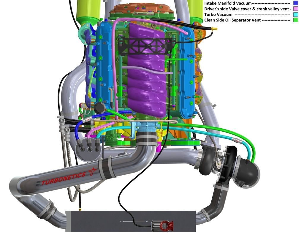
Now the diagram is of a LS engine, so you simply replace the oil fill cap with our cleanside separator and it has a line that runs to the main air filter on your procharger.
The valley cover barb will run direct to the center (inlet) of our "can", one outer fitting with checkvalve flowing away to the intake manifold vacuum barb located on the driverside of the intake manifold snout, and the other outer fitting w/valve flowing away from can to the turbo or centri head unit inlet. You now have the most effective air/oil separation on the market, you are pulling evacuation suction at all times instead of just idle and deceleration, you do not allow pressure to build in the first place, and are keeping most of the contaminants that cause wear from ever reaching your engine oil.
Let us know if you have any questions!

Elite Engineering USA
|
What part number for use with a procharger??
|

|

|