Success! Pics and details to come..... I did not get many thorough pics... Sorry... had a monsoon roll in and rushed through some steps.
Remove the ground battery terminal before starting... give your system type to dissipate...
I think the next obvious first step is to make sure you have all of the parts ready and set aside.
Then... remove the radio display and the dash trim pad... See pictures. A plastic trim tool was used to pry the radio buttons bezel up.


Then.... look at the PDF "Instrument Panel Upper Trim Panel Cover Replacement" ... This gives you all of the steps to remove the front and top panels.
Use an angled 7mm tool or a ratchet to get the "windshield side" screws out.

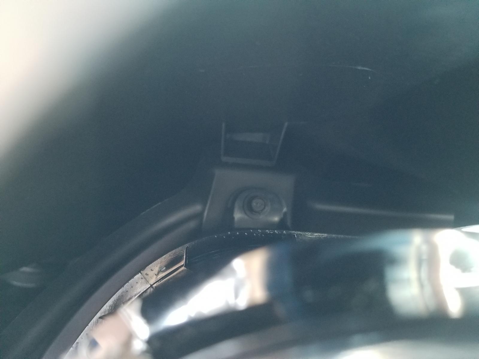
Remove both pilar trims. Be careful on the driver side. There is a microphone in the top section that is only hot glued in. Pop the top clips out just hard enough to get to the wire.


The front panel has a leather piece under the cluster... be very careful prying that up. See photos I did with the trim tool.


Now that the panel is loose... remove the plugs from the Start button and the dimmer switch. Both have release tabs. Power switch is on the side facing the passenger.

If you are using the original panel and adding the HUD switch, there is a cutout line on the back... I used a dremel with a drill bit style cutter to cut the hole out. Be very careful not to go too far out of the lines.


I replaced my top dash cover... but you can cut out the HUD Bezel area with the guide lines under the cover...

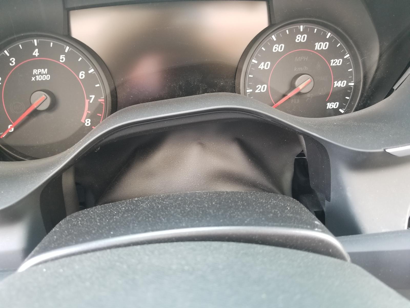
Now... you should be able to remove the instrument cluster. If you removed the cluster before removing the top dash cover... like I did (smh).. ... it's trickier.... Be careful when attempting to access the top 2 screws. You need a long extension... and a magnetic tool to grab the screw so it isn't lost.

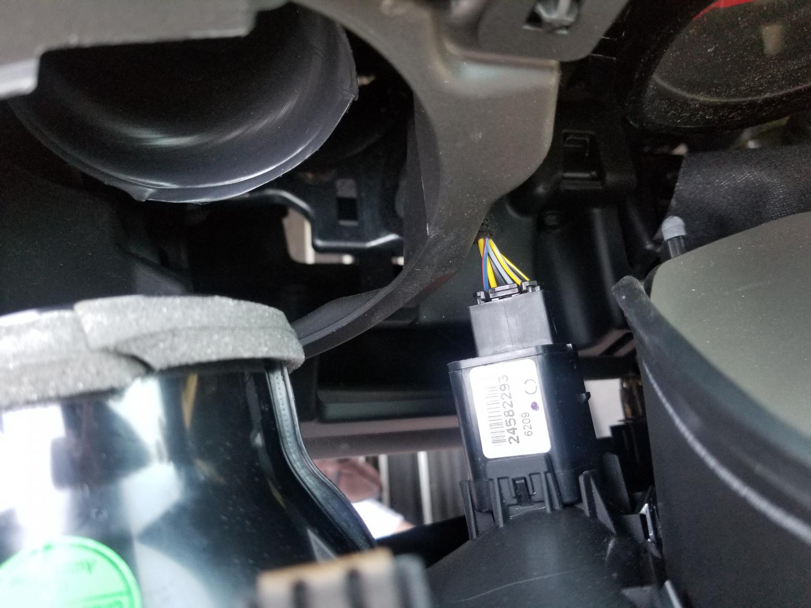
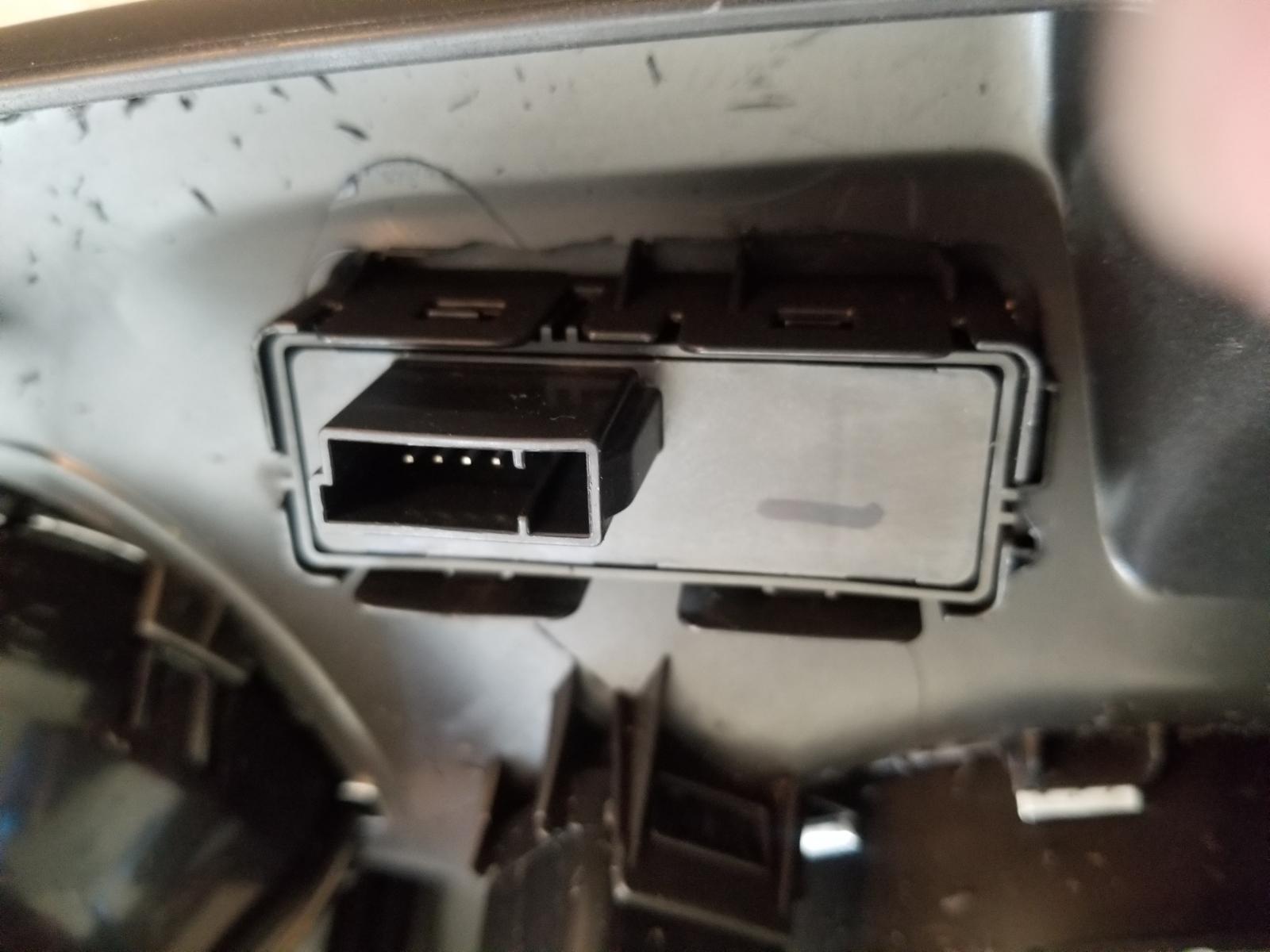
The first connector to remove on the back of the cluster is the USB cable. This is closest to the passenger side of the vehicle. Then the main data/power cable. This has a swivel type lock. Pry up the tab so that it swivels over the connector and slides out of the socket. The only photo I took was on how to get the connector apart to add the necessary wires. You can see the swivel locking mechanism already "bent back". Using a small plastic trim tool... you can pry the connector apart.

Here's where I lost time and photos. Sorry. Mounting the HUD to the metal frame wasn't bad. There are 4 mounting points. The 2 closest to the driver have 2 holes each. The OUTER holes is where the screw "nuts" go. On the 2 holes in the back of the dash (window side), there is only 1 hole. Place these nuts in the small cutout area already there as guides. Do not complete the assembly until you fully integrate the 8 pin wire. You have 1 wire going from X1 pin 1 to the instrument cluster X1 pin 21. I purchased a pack of terminals (listed in the parts list) and crimped the wire direct so that it can go into the cluster easily. The power wire was T-tapped off of the Red/BU wire in the instrument cluster X1 pin 7. Ground was T-tapped off of the cluster as well. X1 pin 19. Wire up the switch controls per the diagram. I just used barrel connectors for that.

EDIT: I forgot to add... If you read the diagram properly, you'll note that the 4 wire switch connector for the HUD switch has 1 wire going to LED Dimmer control. This will be tapped off of the dimmer knob just above the switches. Pin 5 ... solid yellow wire.

For the HUD... that's pretty much it. However, since I have the UHS display now... I had to get the MOST wiring done so that the radio/nav etc worked. This is where it got tricky. At first I figured I would just tap the harness behind the cluster. This was way too tight of an area. So.. I noted that the wires were a twisted pair. White/Grn and Gray/Vt. One set of wires goes from the HMI to the Cluster... and the other comes from the radio to the amp... to the cluster. For the standard cluster, these wires bypass it and go from the radio to amp... and amp to HMI.
The best place of access is the driver side floor trim by the door. See photos. I inserted a staple (yeah... small wire) into pin 2 of X2 of the HMI.... and wrapped a wire around it and 1 end of my meter. Then after pulling the trim apart and accessing the wires... I found the colors needed. Pin 2 of X2 is the white / green wire. Twisted pairs... you should find 2 pairs. Slightly pierce the jacket of one of the white / green wires with your meter until you find the correct pair going to the HMI. Once found... cut both that wire and the gray /purple twisted with. Then run 2 sets of twisted wires going from the cluster to these wires. Pins X1 17 and 18 to to the wires closest to the front of the vehicle (going to the HMI). Pins X1 1 and 2 go to the wires going to the back of the vehicle (amp).

MOST Control is on X1 pin 5 of the cluster. Since I had the IO5 originally... my wire existed.
I know I missed a few steps... but wiring the switches and taping / wire tying is the rest. Then the reverse for re-assembly.
Will edit more later....